1 / Dissertation Consultation
2 / Identity Map–Arduino Experimentation
2 / Voices as Personality– Arduino Experimentation
DISSERTATION CONSULTATION
Notes
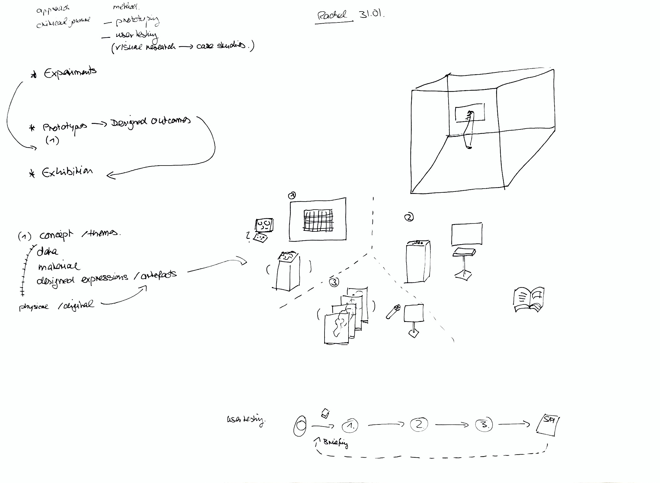
–For the layout of the dissertation, better to place the text first before the image in order to give context/explanation before looking at the visual
–For the mechanics section it should be named technical insights/overview
–User experience section should cover what will happen and what has happened
–It would be good to have a book to compile the data in
User testing can focus on the ability of the prototypes (how easy it is to use the interface, test the effectiveness of how intuitive the prototype is)
–For the prototypes,it can be explained that this is an example of how a scientific study could be conducted
Situating the project
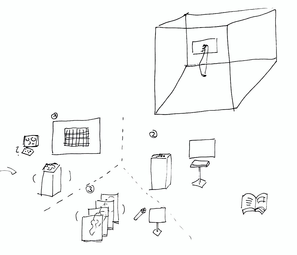
–Look at it from an exhibition perspective–what can be used to improve intuitiveness? Through the use of physical potentiometers or one button + a knob, or the use of sliders instead of a keyboard?
–Another way is to approach it from an aesthetic perspective for people to choose from
–To do so, you should simulate the experience into the exhibition or situate it in an exhibition space (need not actually set it up, you can create it in a 3D software to give a visual of how it will look like)
This was also something that was brought up during the Global Design Initiative Interview, where Nur suggested for me to think in the direction of how can my prototypes be used and experienced by others on a normal basis?
This led me to think of positioning my prototypes beyond an exhbition setting and instead in a public space such as banners at the bus stop or an application, whereby users are able to access and test out these identity tools to determine their emotion or behaviour at that time.
Despite there being two possible directions in which I could situate my prototypes in, I think these two directions actually helped to broaden my thinking alot. Prior to this, I only thought of having my prototypes collated within a mobile app or website which was quite limiting. Now with these two suggestions, I feel like there's more room for me to push my project further in terms of an exhibited project or something that is closer to the user, be it in a public space or a tool that can be conveniently accessed. Or it can be both–a project that exists within an exhibited space that can also be adapted into tools.
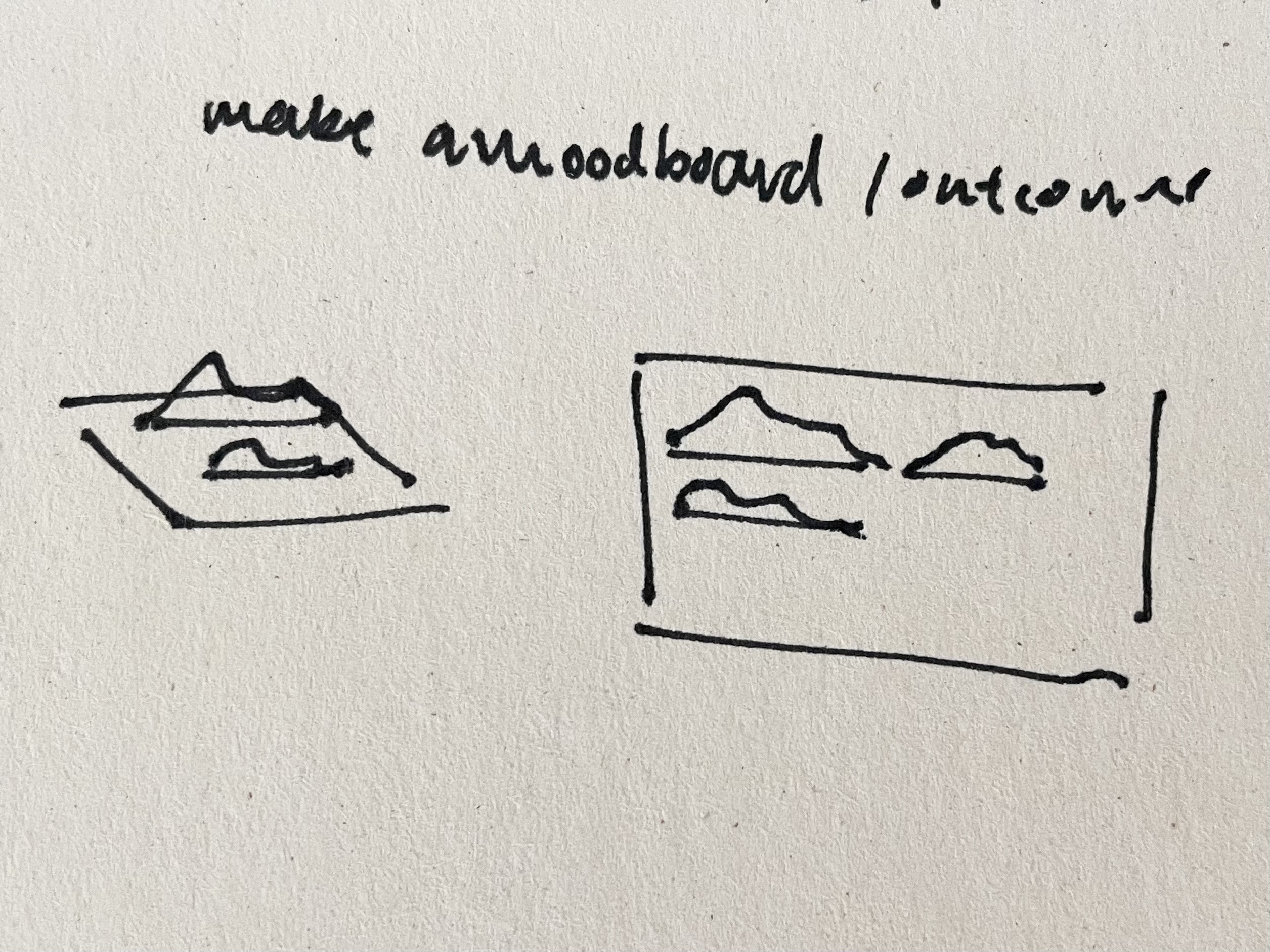
Matin had also suggested the use of the laser cutter for the Identity Map physical artefact. In the above sketch, it illustrates how the slices of the grid can be materialised in the form of acrylic sheets and then laser cut to form the individual rows of the grid. When put together, it should form the identity map. I thought the use of laser cutter would be pretty helpful and efficient, hence this might be a possible way of crafting the physical artefact at a later stage.
IDENTITY MAP PROTOTYPE ARDUINO EXPERIMENTATION
From the dissertation consultation, I realised that my prototypes do lack a sense of intuitiveness and additionally, the use of keyboard as the main source of input made the user experience feel quite repetitive. Hence, I wanted to try attaching potentiometers and other Arduino tools in order to enhance the intuitivity of the prototypes and create a more efficient user testing experience as well. Furthermore, the point on focusing user testing on the intuitiveness of the prototypes also caught my attention as I do think that by including this portion in my writing will help to portray the prototyping progress in more detail.
This being my first attempt at Arduino, I think after tons of tutorials, videos and articles which I’ve read has sort of given me an idea of how to Arduino works, and what I need in order to execute my setup. However, for the initial set up I was quite lost as to how the circuit works, so the below links really helped me visualise how the circuit board is being used and what the terminals function as.
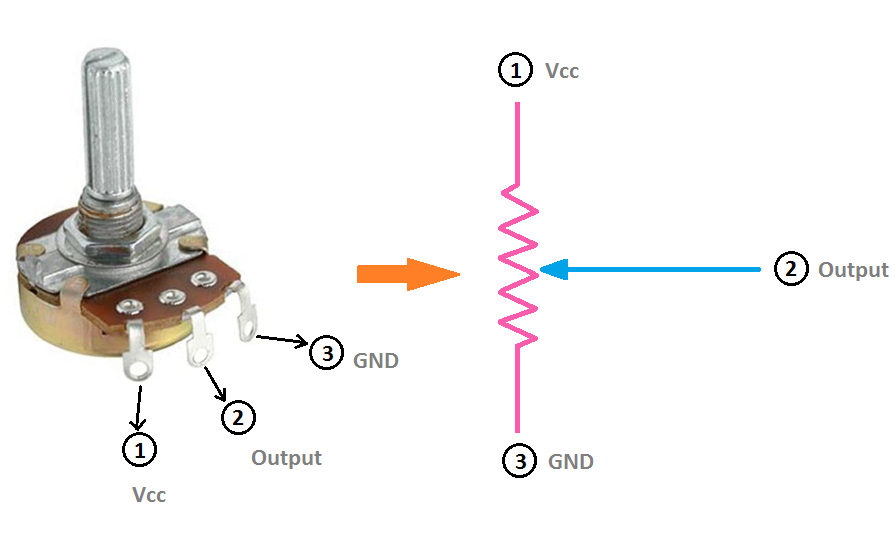
Image: Potentiometer Circuit Connection & Diagram. ETechnoG. 2019.
Comparing different devices
Here's a tutorial using MIDI controller instead of a potentiometer which I found interesting as well, and may be one of the options to consider for future developments.
I also looked into rotary switches and considered how they can be used as compared to the potentiometer
But from an article that I read, the potentiometer seemed more appropriate as I wanted to measure a specific range of value inputs as compared to a rotary encoder which provides an infinite rotational range.
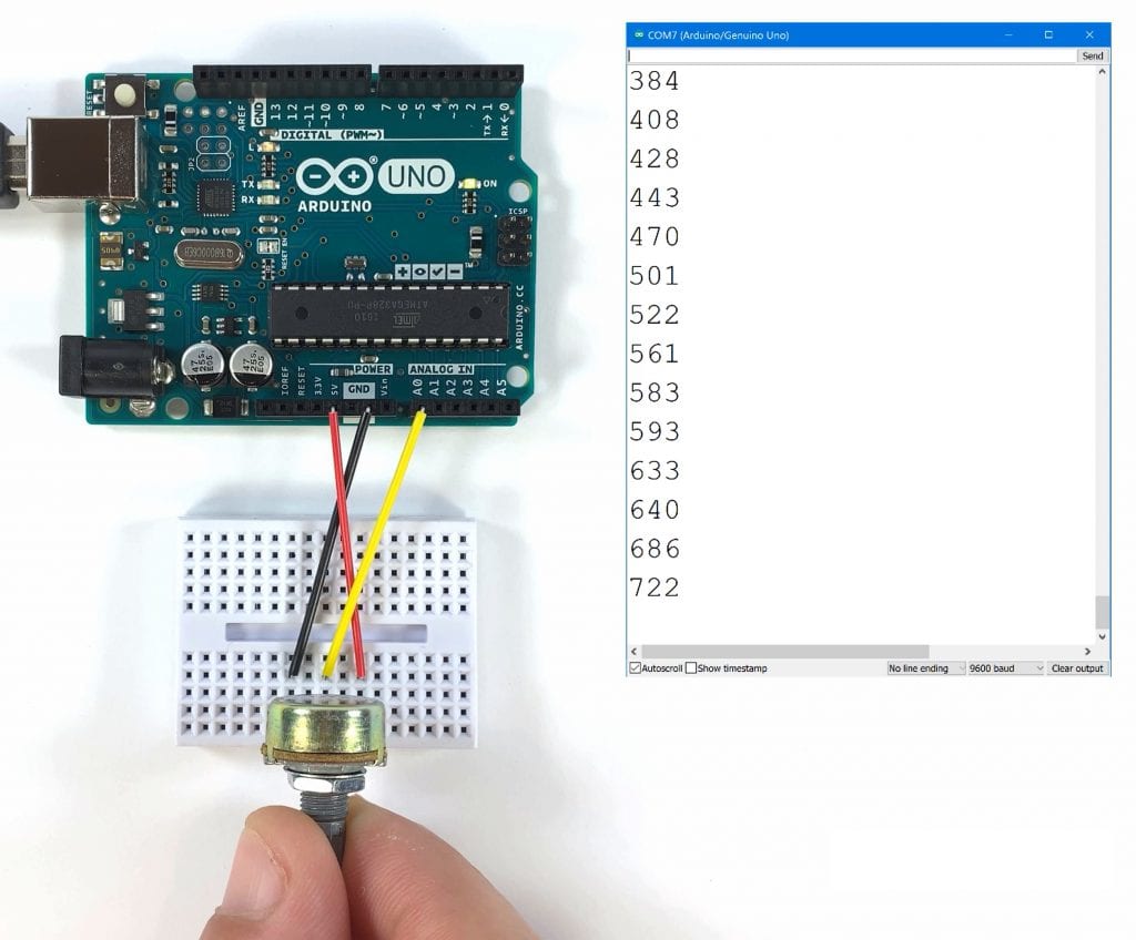
Image: How To Use Potentiometers On The Arduino. Scott Campbell Scott Campbell. Circuit Basics
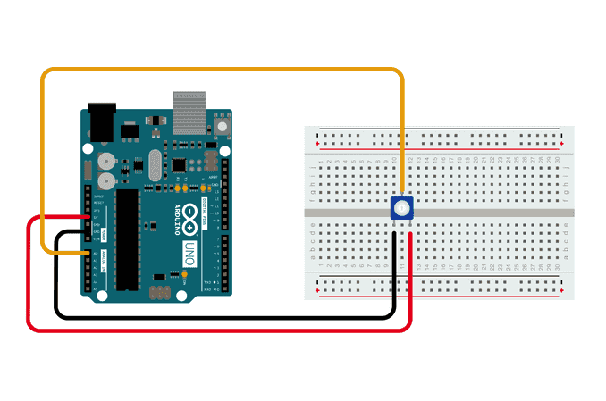
Image: Analog Read Serial. Arduino Documentation. 2023.
I started off with connecting a 20K potentiometer that was bought from SunLight Electronics. The set up was pretty straightforward, after referencing the above two diagrams, I was able to quickly complete the circuit and connect the input data to Touchdesigner.
Here the potentiometer values range from 0 to 1023, and when the knob is being rotated, the values change accordingly.
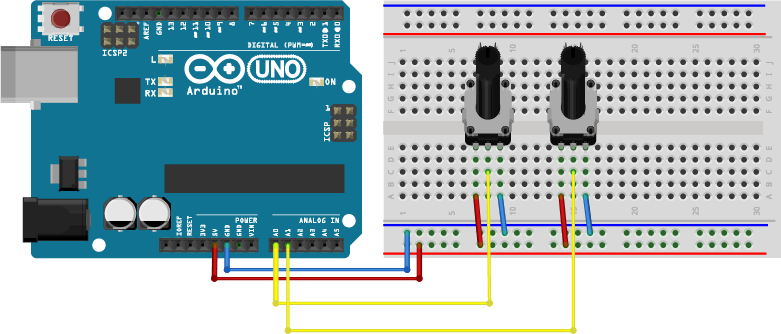
Image: 2 Knobs 1 App. Involt.
The challenge here was to connect multiple potentiometers to the circuit, have Arduino recognise the different data input and categorise them under different channels within Touchdesigner. Luckily, I managed to find a diagram with at least two potentiometers which I made use of to connect four potentiometers. Also, I preferred the layout of this circuit as the jumper wires and arduino board can be aligned behind the potentiometers which will be beneficial when we need to conceal the wires for packaging.
As there aren't any tutorials on how to write the code to receive data for multiple potentiometers, I searched up Touchdesigner forums to see if there are any similar codes that I could reference from. Below, are some of the forums which I found quite insightful.
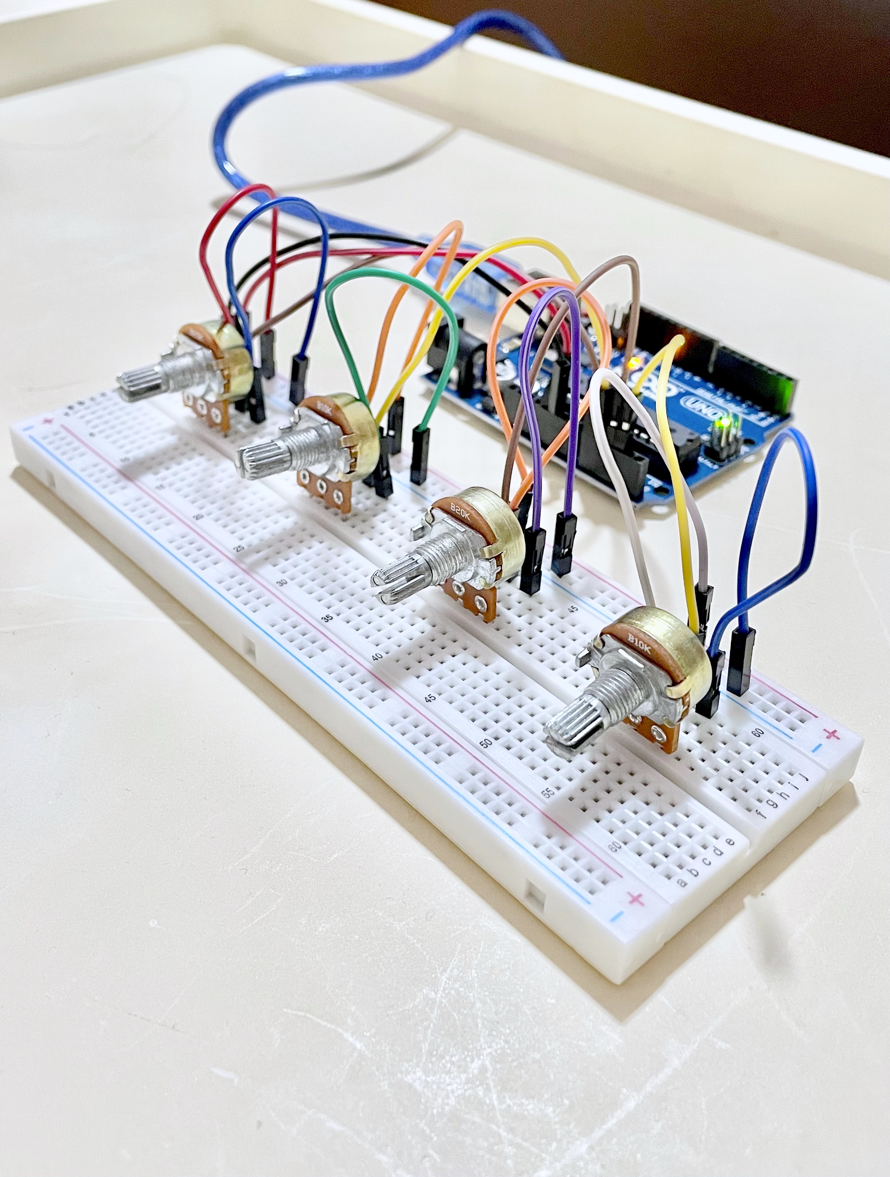
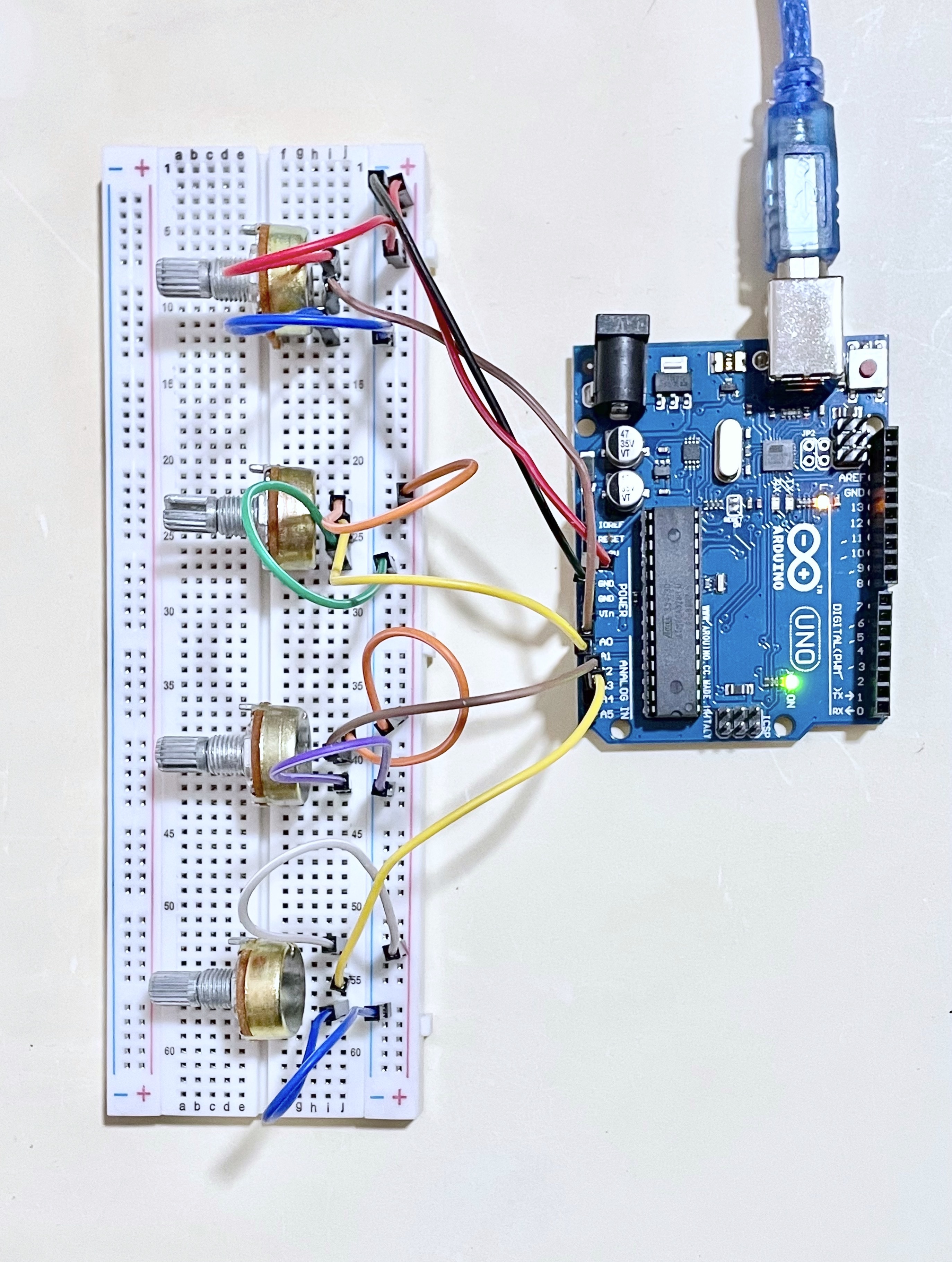
ARDUINO + TOUCHDESIGNER
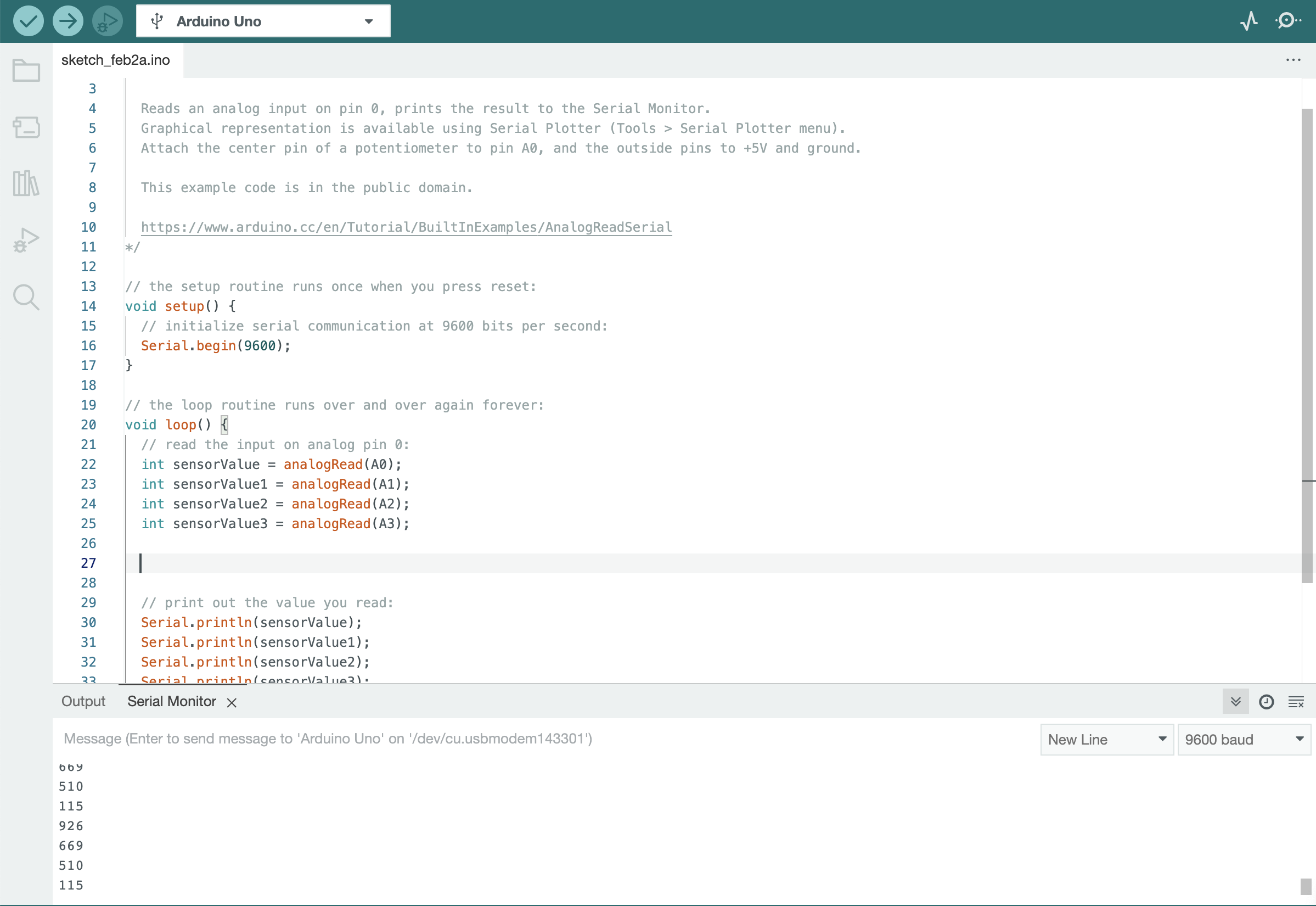
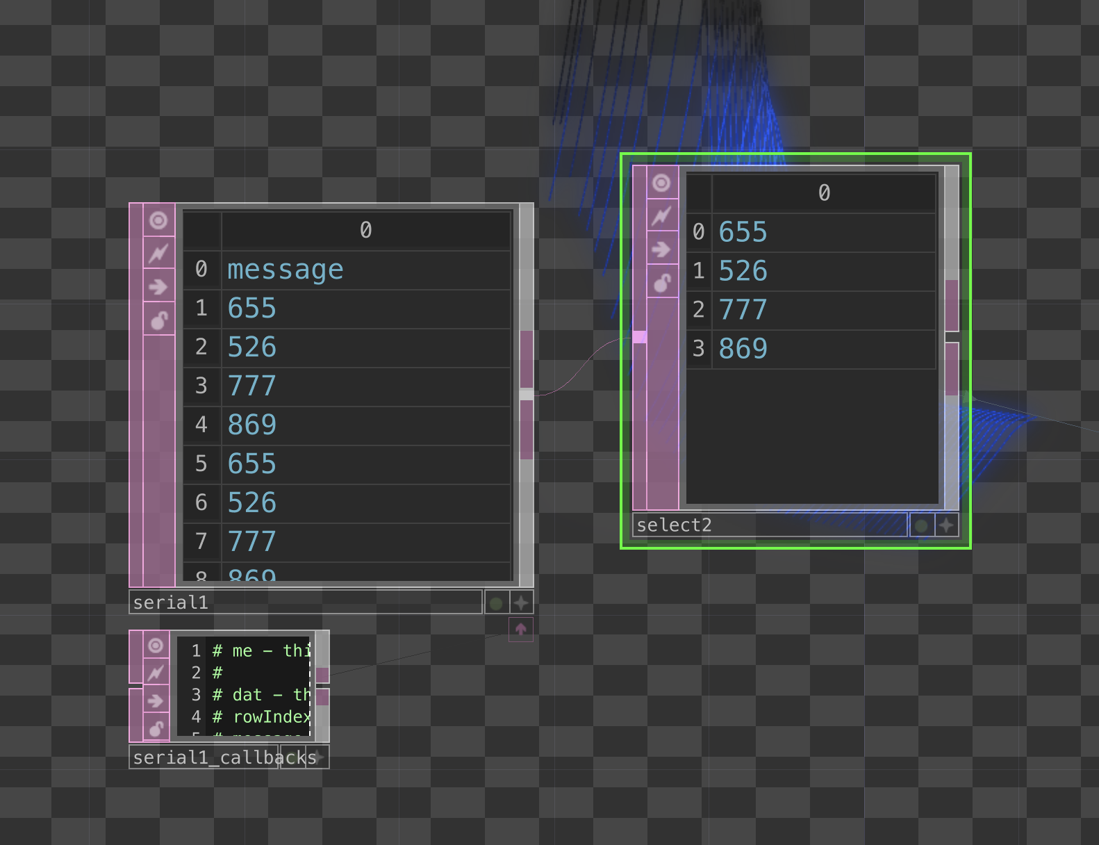
By following references on how to write data inputs into an array, this helped me to receive and send over multiple potentiometer values into Touchdesigner and sort them into different rows, which would be helpful when translating these data into channels that can be used to control different variables.
VOICES AS PERSONALITY PROTOTYPE ARDUINO EXPERIMENTATION
Setup Reading & References
Microphone CircuitConnecting ardunio sound sensor as a microphone device
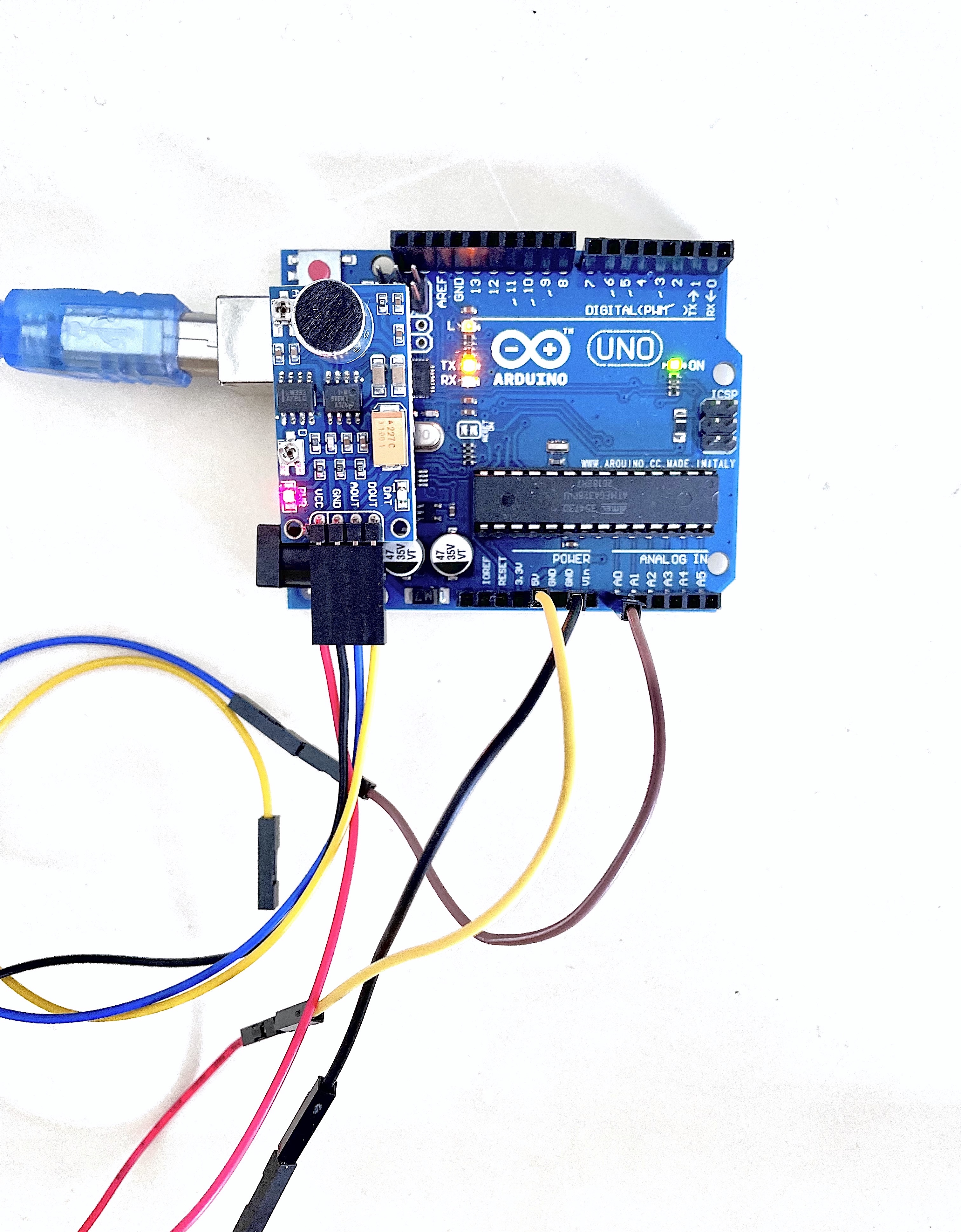
For the microphone circuit, it was much simpler to set up as compared to the potentiometer as I only needed one source of sound input to control Touchdesigner. However, there were still some difficulties with the set up as most of the tutorials online skipped the part about the connecting the jumper wires. Thus, as up till this point I've only worked with m/m jumper wires, I struggled with the m/f jumper wires that came with the sound sensor. Hence as can be seen in the below image, I resorted to using the breadboard to connect the microphone and the arduino circuit.
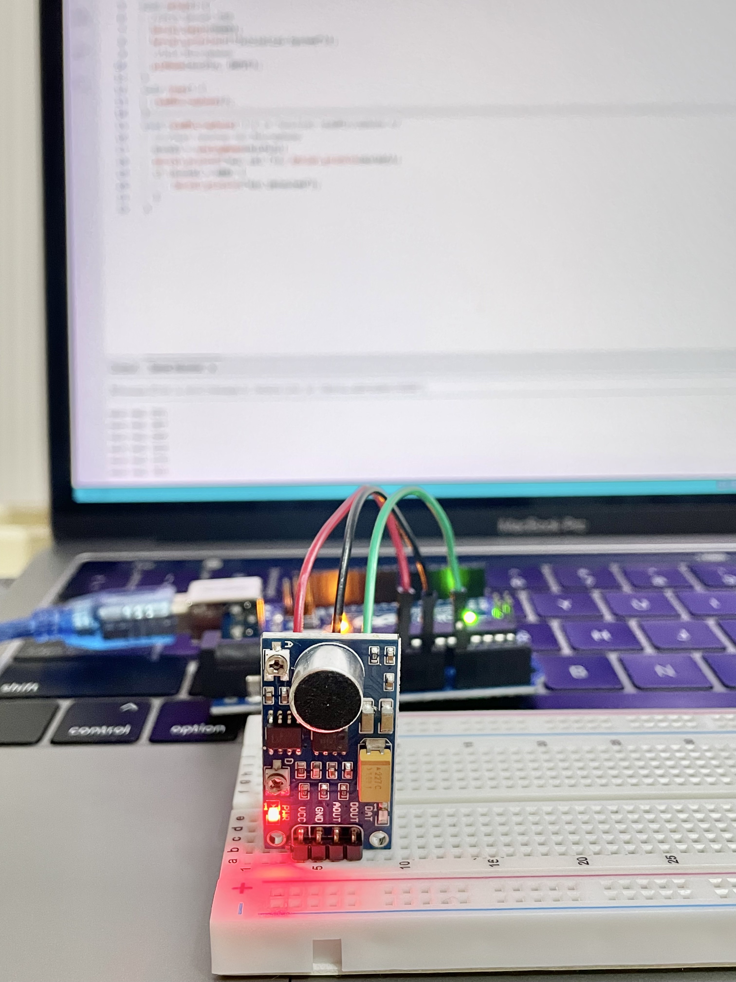
Image: Microphone Set Up 1.
But after consulting my friends the next day, I found out that the m/f jumper wires could actually be connected to another m/m jumper wires in order to directly connect to the arduino circuit itself. This way of setting up really helped to reduce the bulkiness of the circuit, which can be useful when it comes to packaging the prototype later on.
Image: Microphone Set Up 2.
